Constructing the physical parts of the cluster is fairly straightforward once the mounts are printed.
Printing the Switch Rack Mounts
Each mount should be printed with PLA. I used a .4 mm nozzle on an Ultimaker 2+ Extended (any printer should work though). The STL files are located at the top of this page under "Project Files".
Putting it all Together
As can be seen in the image below I used three parts of the GeauxRobot Dogbone case: one on each end and one in the middle. This allowed for good rigidity throughout the structure.
I then used M3 standoffs for the connecting rails.
The PIs themselves are mounted to either the left or the right Dogbone with M2.5 x 10mm + 6mm standoffs between the boards (including the POE hats).
Connecting the Electrical
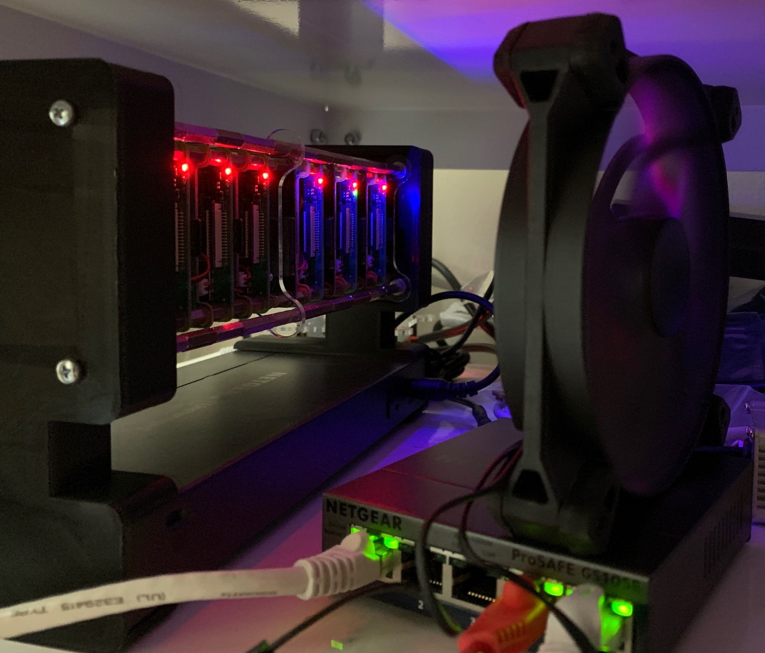
Once the physical structure is in place go ahead and connect the 6" ethernet cables to the switch and each PI. Connect your network to the far right port of the switch.
Finally, connect up the power cable and watch the PIs come up.
Regarding the optional cooling fan - it is not required but I found it to MUCH quieter with than the POE fans. For now I have that standing on another small switch behind the cluster. I'll work on adding mounts for that fan and it's power supply at some point in the future. If you choose to add the fan be sure to angle it slightly so that all the PI "blades" get air pushed across them.

